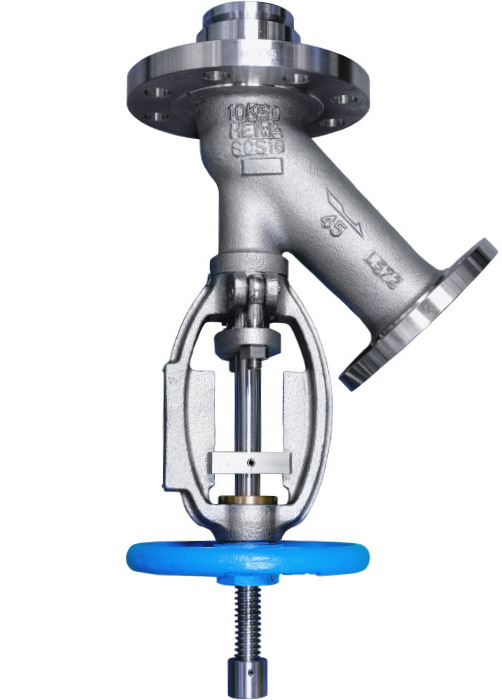
The Flush Bottom Tank Valve is usually installed at the bottom of a reaction tank of the factory equipment to drain the fluids out of the tank.
The "Y-type Flush Bottom Tank Valve" series is one of our main products.
This series of products are high-value-added valves with a wide selection of special features that can satisfy the diverse needs of customers’ special specifications and service environments.
* Click on the blinking • to see the explanation.
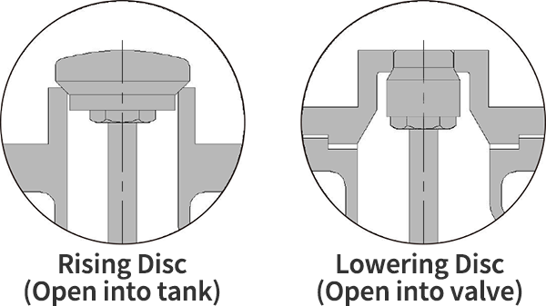
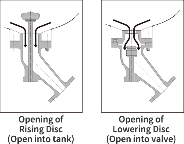
Two types of valve disc
We can also classify flush bottom tank valves by the method to operate the valve and control into two major types. One is by pressing the valve disc against the valve body seat to shut off the flow path of the fluid. The other is utilizing the fluid pressure to seal off the flow path.
Wide range of designs of flange sizes to match different pressures
Efficient discharge structure
To eliminate this drawback, our flush bottom tank valve has a common design feature: the size of the inlet flange is larger than the size of the outlet flange to allow faster discharge.
Excellent corrosion resistance and abrasion resistance
Non-rotating stem type
Our standard gland packing is made of PTFE. Gland purge is available as an option.
Actuation according to service environments
In recent years, extensive use of automatic actuated valves in plant equipment is the trend to achieve plant safety through centralized and automatic control. We have a wide variety of products to handle various fluid control issues.
For actuators and options, refer to the product series in this catalog.
DISC SHAPE AND VALVE SEAL
The valve disc is the essential part to perform the function of opening or closing a flush bottom tank valve. The valve is closed when the valve disc is forced to tightly contact with the valve seat to shut off the flow path. Therefore, performing reliable fluid control functions and preventing leakage from the valve seals are important considerations for designing a good flush bottom tank valve. When a leakage from a valve occurs in a piping system, it not only may cause problems at the downstream, but may also have a severe adverse impact on its upstream production.
Because the valve seat is greatly affected by the compositions and temperatures of the fluid, it is extremely important to select the right material to make the valve seats according to the requirements of the fluid conditions and applications.
Based on the material for manufacture the disc and seats, our tank valves can be divided into two types: "Metal Seated" and "Soft Seated".
*The pictures below show the rising disc type valves.
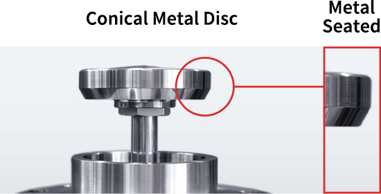
Because the valve disc and the valve seats are made of metal, this type can be used to service high-temperature fluids.
Furthermore, by applying welding or other types of hard-facing treatment to the seats, this type of flush bottom tank valve is better equipped to service viscous and slurry fluids.
- Seat hard-facing treatment (Co-Cr-W)
- Hard-facing treatment only for the designated wetted area (Co-Cr-W)
- Hard-facing treatment for the entire wetted area (Co-Cr-W)
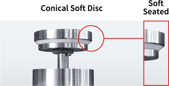
The seats of this type of valve are made of non-metallic material.
The soft seats are less worn by abrasion and can maintain high sealing performance. Besides, the PTFE resin used in the seat can be easily replaced for maintenance.
However, this type of soft seated flush bottom tank valve performs poorly if the operating temperature exceeds the allowable heat resistance of the seats, and thus their applications are limited by service conditions.
* Please check your maximum operating temperature before specifying the tank valve.
LIST OF MATERIALS
| BODY (CASTING) | TRIM (STEEL) |
|---|---|
| SCS13A (JIS G 5121) | SUS304 (JIS G 4303) (JIS G 4318) |
| SCS14A (JIS G 5121) | SUS316 (JIS G 4303) (JIS G 4318) |
| SCS16A (JIS G 5121) | SUS316L (JIS G 4303) (JIS G 4318) |
| BODY (CASTING) | TRIM (STEEL) |
|---|---|
| SCS10 (JIS G 5121) | SUS329J4L (JIS G 4303) (JIS G 4318) |
| SCS11 (JIS G 5121) | SUS329J1 (JIS G 4303) (JIS G 4318) |
| SCS18 (JIS G 5121) | SUS310S (JIS G 4303) (JIS G 4318) |
| SCS19 (JIS G 5121) | SUS304L (JIS G 4303) (JIS G 4318) |
| SUS317L or equivalent casting material | SUS317L (JIS G 4303) (JIS G 4318) |
| SCS13 (JIS G 5121) | SUS304 (JIS G 4303) (JIS G 4318) |
| SCS14 (JIS G 5121) | SUS316 (JIS G 4303) (JIS G 4318) |
| SCS16 (JIS G 5121) | SUS316L (JIS G 4303) (JIS G 4318) |
| BODY (CASTING) | TRIM (STEEL) |
|---|---|
| CF8 (ASTM A 351) | SUS304 (JIS G 4303) (JIS G 4318) |
| CF8M (ASTM A 351) | SUS316 (JIS G 4303) (JIS G 4318) |
| CF3M (ASTM A 351) | SUS316L (JIS G 4303) (JIS G 4318) |
| CF3 (ASTM A 351) | SUS304L (JIS G 4303) (JIS G 4318) |
| BODY (CASTING) | TRIM (STEEL) |
|---|---|
| CW12MW (ASTM A 494) | ALLOY C-276 / MA276 |
| CX2MW (ASTM A 494) | ALLOY C-22 / MA22 |
| N12MV (ASTM A 494) | ALLOY B / MA-B |
| N7M (ASTM A 494) | ALLOY B-2 / MA-B2 |
| MC ALLOY | MC ALLOY |
| MAT21 | MAT21 |
| Nickel * track records of casting available |
| Titanium |
| Zirconium |
| Carpenter® 20 |
| Inconel® 600 |
| Tantalum |
| ALLOY 20 |
| Seat hard-facing treatment (Co-Cr-W) |
| By welding high-hardness Co-Cr-W alloy on the surfaces of the valve body seat and disc seat, both seats are hard-faced to prevent damage to the valve seal. Upon request, it is also possible to use a soft material such as PTFE for the disc seat and only apply hard-facing treatment to the valve body seat. |
| Hard-facing treatment on specified wetted area (Co-Cr-W) |
| A high-hardness Co-Cr-W alloy is welded to the specified location. We will harden not only the surfaces of valve seats but also the specified wetted area. |
| Hard-facing treatment on the entire wetted area (Co-Cr-W) |
| A high-hardness Co-Cr-W alloy is welded on the entire wetted area. |
* Certain valve parts and locations are not possible to apply hard-facing treatment. Please contact us for your required hard-facing treatment.
| PTFE (Polytetrafluoroethylene) |

This option selects PTFE as the material for the valve seat. PTFE is chemically stable, has excellent corrosion resistance and heat resistance, and has high sealing performance.
Color: White Maximum operating temperature:100°C |
| GF PTFE (PTFE filled with glass fiber) |

As compared to PTFE without filler, this optional material, glass-filled PTFE, has superior creep resistance and heat resistance.
Color: Milky White Maximum operating temperature: 120°C |
| CF PTFE (PTFE filled with carbon) |

As compared to PTFE without filler, this optional material, carbon-filled PTFE, has superior creep resistance and heat resistance.
Color: Black (no gloss) Maximum operating temperature: 150℃ |
| PTFE+PFA |

This optional material is an extremely superior material that combines the heat resistance and chemical resistance of PTFE with the properties of PFA.
Color: White (slightly translucent) Maximum operating temperature: 200°C |
| PTFE+PFA |

Color: White (translucent)
Maximum operating temperature: 200°C |
| Hard Graphite |

Hard graphite is a material made by molding graphite (black lead) at high temperatures and high pressure, so it can be used at high temperatures. It has heat resistance and self-lubricating properties.
Color: Black (glossy) Maximum operating temperature: 400°C |
| Chloroprene Rubber |

Chloroprene rubber is a rubber that is superior to natural rubber in heat resistance, oil resistance, and chemical resistance.
Color: Black (no gloss) Maximum operating temperature: 90°C |
* The information on maximum operating temperature is provided by the manufacturer. The maximum operating temperature may be varied depending on shapes and sizes. If you have any questions about your selection, please feel free to contact us or our agents in your area.


